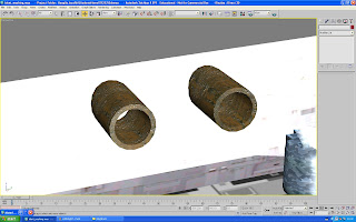
 ^Creating the beginnings of the portholes meant creating tubes first of all. Of course, I need to select not only the outer edge dimensions, but also the depth at which the tube's inner circumference/diameter would reach. Once I had chosen this, it was a case of rotating them to lay flush against the side wall of the kitchen interior (these were just going to be for decoration, but the idea to use them as windows was suggested to myself, for which I was grateful for the input!)^
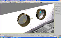
Note: I already found an ideal texture in Max's default library for the tubes. As you can see in this image, it gives them a definite feel of aged ironmongery in a space-age environment!
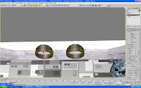 I then added a 'UVW Map' onto the original and the cloned tube - both aptly named pipe01 and pipe02. The face mapping proved effective, and I also took this chance to increase the number of sides to smooth out the form of the pipe so as to appear less angular around the edges!
I then set the pipes up against the wall and slowly merged them inside to cover the interior depth. I then knew I had to create
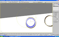 another set of two tubes for the Boolean modifier - these were based on the measurements of the pipes already set-up, but with a decrease in the overall diameter so they could fit inside pipes 01 and 02
As the image shows, all that was needed was too decrease in the interior circumference to 0 to achieve a solid object to use as Operand B
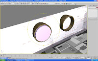
The image shows that by making the inner tube fit inside the outer one as equally as possible and cloning it, if the cloned version of, for example, pipe 01 is the same dimensions too, then all would be well for an accurate Boolean.
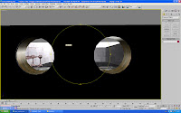
With the wall as Operand A and by subtracting a material from B,
a tidy Boolean was
 achieved as shown the the second image
Although, initially I had a bit of trouble as the inner tube stayed where it was and kept taking on the material used in the wall, the wall which disappeared (I then found out I had 'Subtraction of B from A' checked and 'Move' instead of 'Instance' - a simple mistake I was told!)
 ^A view inside the kitchen from the new porthole windows...just to prove it worked!^
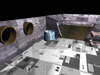 ^ A rendered update on the interiors - not too shabby I don't think (as an idea, instead of a roof, I may just construct a horizontal plane a couple of steps above the ceiling's upper edges and cover it with a starry-like texture)^
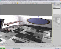 A porthole was intended for the opposite wall which would be looking out onto the Moon's surface and the Earth in the far distance (an image which I will present further down in this post...)
The process that was used in the making of the other two is repated here, with a tube generated and staeched alog its 'x' axis so that it transformed into the shape shown to the left
Again, another cloned version was created to fill in the gap between the shape (a little more difficult this time due to the irregularity's of the form!)
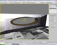
But after learning what I had done wrong the first time I tried it, the Boolean was completed ahead of time and all that was needed was minor adjustments to the dimensions of the porthole to fill in the gap nicely
I also made small tiling adjustments to the material and increased the sides of the tube for a smoother look
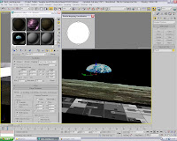 ^ After importing the image I had saved into the Library, I knew I would need to alter the tilings and perhaps use the 'Rotate_Mapping_Co-ordinates' tool, which meant I could tip it to one side and make it seem that Si's house would be following the curvature of the planet itself^
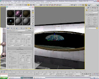 ^I also tried to display the texture as an environment map, but I found its not possible to edit it in terms of repositioning, which was a shame as it was very believable if the camera was angled correctly during the rendering process. Here it is displayed outside as you should see it during the render, but I may need some external lighting to show it against the internal lights...^
Tutorial on Havok Engine
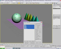 ^ The first step is to create a plane and angle it downwards. Then add, on one end and just hanging over the edge of the plane, whichever objects you want to have topple over. Then create a ball which will contain the relevant mass figure that can knock them down!
After this, go to the Reactor menu and select 'create rigid-body collection' and highlight all the objects in the scene that you will include in this test...^
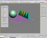 ^Before you move on to the next part, go to the reactor menu and select 'Rigid-Body Properties' By then selecting the plane and making sure its 'simulation geometry' is checked as 'Concave-Mesh', the plane will actually suspend any objects above it (not doing this means all the objects sitting above it will fall through immediately as the animation runs!^
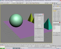 ^The menu is displayed in the image here. You can actually selected any image in the scene and its individual settings will update in the menu
This allows to batch-select items which you want to have identical properties e.g. the pyramids in the scene here which, incidentally, you must make sure are not bisecting either each other or plane itself^
 ^The last step before a preview animation takes place is to finalize the settings for the sphere. By increasing the default settings for the mass to 50 points and the 'simulation geometry' to 'Bounding-Sphere', the ball will now react as you would expect in reality (the Havok engine accurately recreates real-world physics in a computer-generated motion sequence!)
Once the test is successful, you can then feel free to alter many other settings such as 'friction', which denotes the resultant force that acts on objects in real-life which have irregular groups of atoms at the surface and 'elasticity', the measure by which the object's opposing forces engage once it has come into contact with another object^
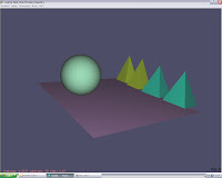 ^The screen you see once you have selected 'preview animation'
You may get errors occurring, with many differing causes; from a simple thing such as an object bisecting another as we discussed, or to something more complex such as a misuse of an objects properties, perhaps using numbers far in excess of the program's capabilities!^
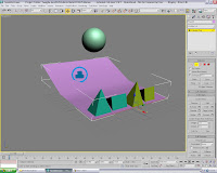 ^Once you have a simple animation working, you can then experiment with set-ups such as this slightly precarious situation. The actual 'rigid-body' symbol shown below the ball doesn't actually have to permanently attached with the ball, as all it does is show there is a 'rigid-body' object in the scene, and all you do is select it and it will show its twinned object^
The Idents are coming together nicely, and I'm certain about what they will all involve. Next week I can finished Si's design and try a few tentative steps of animation on his arms and tentacles - should be a interesting learning curve!

No comments:
Post a Comment